While I'm building infrastructure via helm/kubernetes, I feel like most important factor for success is 1. networking, 2. pv/pvc ( Persistent Volumes and Claim ) 3. Authorization and Authenticiation. Especially networking, it bothers me all the time while I'm doing trouble shoot the cluster, here I would like to share my personal note for kubernetes networking which helps me or someone can take advantage from it.
The very heart of kubernetes’ design requires that pods be able to communicate with other pods whether they are running on the same local host or separate hosts. When I built my kubernetes with applications, I alway need to circle back to this note to refresh my kubernetes network knowledge.
Pods Networking
Flexible Docker helps Kubernetes Pods
What's Pods: A pod consists of one or more containers that are collocated on the same host, and are configured to share a network stack and other resources such as volumes.
physical network interface eth0. Attached to that is a bridge docker0, and attached to that is a virtual network interface veth0. Note that docker0 and veth0 are both on the same network, 172.17.0.0/24 in this example.
172.17.0.1 ( bridge docker0 ) and is the default gateway for veth0, which is assigned 172.17.0.2.
The second container ( container 2 ) gets a new virtual network interface veth1 (172.17.0.3), connected to the SAME docker0 bridge.* This interface is assigned 172.17.0.3, so it is on the same logical network as the bridge and the first container, and both containers can communicate through the bridge as long as they can discover the other container’s IP address somehow.
Sum: docker0 is the default gateway for veth0/veth1 and both container 1 and container 2 can communicate through docker0 ( as bridge ) and discover each other by 172.17.0.2 and 172.17.0.3 IPs.
Docker is flexible and can start a container and rather than creating a new virtual network interface for it, specify that it shares an existing interface. In this case the drawing above looks a little different:
Now the second container sees veth0 rather than getting its own veth1 as in the previous example.
This has a few implications:
- First, both containers are addressable from the outside on 172.17.0.2, and on the inside each can hit ports opened by the other on localhost.
- This also means that the two containers cannot open the same port, which is a restriction but no different than the situation when running multiple processes on a single host.
Sum: In this way a set of processes can take full advantage of the decoupling and isolation of containers, while at the same time collaborating together in the simplest possible networking environment.
Last, in kubernetes, the container was started with the pause command. The pause command suspends the current process until a signal is received so these containers do nothing at all except sleep until kubernetes sends them a SIGTERM.
Here is an example. I got kabana pod and when you grep with the pod name you will see two docker containers with that prefix, one is kibana container and another is running "/pause" with "k8s_POD_" prefix.
NAME READY STATUS RESTARTS AGE
pod/elder-marsupial-kibana-6788bfcbd9-9pbtq 1/1 Running 0 18h
$ sudo docker ps -a | grep elder-marsupial-kibana-6788bfcbd9-9pbtq
16a9a3e12a66 98827ed3eefc "/usr/local/bin/kiba…" 19 hours ago Up 19 hours k8s_kibana_elder-marsupial-kibana-6788bfcbd9-9pbtq_default_3e40b3e9-d193-11e8-9568-0214683e8447_0
1d157dd3c3f3 k8s.gcr.io/pause:3.1 "/pause" 19 hours ago Up 19 hours k8s_POD_elder-marsupial-kibana-6788bfcbd9-9pbtq_default_3e40b3e9-d193-11e8-9568-0214683e8447_0
Kubernetes Pod Network
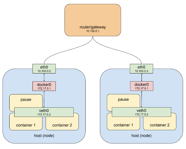
What is kubernetes cluster ? A kubernetes cluster consists of one or more nodes. A node is a host system, whether physical or virtual, with a container runtime and its dependencies (i.e. docker mostly) and several kubernetes system components, that is connected to a network that allows it to reach other nodes in the cluster.
The private network 10.100.0.0/24 for this example, so the router is 10.100.0.1 and the two instances are 10.100.0.2 and 10.100.0.3 respectively.
The pod-like things back into the picture is as below.
The host on the left has interface eth0 with an address of 10.100.0.2, whose default gateway is the router at 10.100.0.1. Connected to that interface is bridge docker0 with an address of 172.17.0.1, and connected to that is interface veth0 with address 172.17.0.2.
The veth0 interface was created with the "pause" container ( each pod has it's own "pause" container ) and is visible inside all three containers by virtue of the shared network stack. Because of local routing rules set up when the bridge was created any packet arriving at eth0 with a destination address of 172.17.0.2 will be forwarded to the bridge, which will then send it on to veth0. Sounds ok so far.
The host on the right also has eth0, with an address of 10.100.0.3, using the same default gateway at 10.100.0.1, and again connected to it is the docker0 bridge with an address of 172.17.0.1.
Hmm. That’s going to be an issue.
Now this address might not actually be the same as the other bridge on host 1. I’ve made it the same here just show it's a pathological worst case
 Kubernetes provides that structure in two ways. First, it assigns an overall address space for the bridges on each node, and then assigns the bridges addresses within that space, based on the node the bridge is built on. Secondly it adds routing rules to the gateway at 10.100.0.1 telling it how packets destined for each bridge should be routed, i.e. which node’s eth0 the bridge can be reached through. Such a combination of virtual network interfaces, bridges, and routing rules is usually called an overlay network. When talking about kubernetes I usually call this network the “pod network” because it is an overlay network that allows pods to communicate back and forth on any node. I’ve changed the name of the bridges from “docker0” to “cbr0.” Kubernetes does not use the standard docker bridge device and in fact “cbr” is short for “custom bridge.”Another thing to note is that the address space assigned to the bridges in this example is 10.0.0.0/14.
For example: The endpoint 10.32.0.4, 10.32.0.6 and 10.32.0.7 is cbr0 here and it's ping-able and can telnet as well since it's a bridge and default gateway from native docker.
$ kubectl describe svc elder-marsupial-elasticsearch
Name: elder-marsupial-elasticsearch
Namespace: default
Labels: app=elasticsearch
chart=elasticsearch-0.1.0
heritage=Tiller
release=elder-marsupial
Annotations: <none>
Selector: app=elasticsearch,component=master,release=elder-marsupial
Type: NodePort
IP: 10.109.120.144
Port: http 9200/TCP
TargetPort: http/TCP
NodePort: http 31328/TCP
Endpoints: 10.32.0.4:9200,10.32.0.6:9200,10.32.0.7:9200
Port: transport 9300/TCP
TargetPort: transport/TCP
NodePort: transport 32088/TCP
Endpoints: 10.32.0.4:9300,10.32.0.6:9300,10.32.0.7:9300
Session Affinity: None
External Traffic Policy: Cluster
Events: <none>
In general, there is not way to figure out and it's only can get if you have service wrap it up.
Service Networking
What's service ? When a pod talks with another pod it most often does so through the abstraction of a service, a kind of software-defined proxy
NAME TYPE CLUSTER-IP EXTERNAL-IP PORT(S) AGE
service/elder-marsupial-elasticsearch NodePort 10.109.120.144 <none> 9200:31328/TCP,9300:32088/TCP 41s
service/elder-marsupial-kibana NodePort 10.106.154.240 <none> 443:30677/TCP 41s
As you can see above when the service is created we can see that it has been assigned an IP address which is CLUSTER-IP and will accept requests on port 9200:31328/TCP,9300:32088/TCP and 443:30677/TCP.
Requests can be sent to the service IP directly but it would be better to use a hostname that resolves to the IP address. Fortunately kubernetes provides an internal cluster DNS that resolves the service name, and with a slight change to the client pod we can make use of it:
$ kubectl get pods
NAME READY STATUS RESTARTS AGE
elder-marsupial-elasticsearch-0 1/1 Running 0 19h
elder-marsupial-elasticsearch-1 1/1 Running 0 19h
elder-marsupial-elasticsearch-2 1/1 Running 0 19h
elder-marsupial-kibana-6788bfcbd9-9pbtq 1/1 Running 0 19h
$ kubectl get pods -o jsonpath='{.items[*].status.podIP}'
10.32.0.7 10.32.0.6 10.32.0.4 10.32.0.8
$ kubectl get pods --output=wide
NAME READY STATUS RESTARTS AGE IP NODE NOMINATED NODE
elder-marsupial-elasticsearch-0 1/1 Running 0 22h 10.32.0.7 helm <none>
elder-marsupial-elasticsearch-1 1/1 Running 0 22h 10.32.0.6 helm <none>
elder-marsupial-elasticsearch-2 1/1 Running 0 22h 10.32.0.4 helm <none>
elder-marsupial-kibana-6788bfcbd9-9pbtq 1/1 Running 0 22h 10.32.0.8 helm <none>
The pod network address range is not exposed via kubectl and so you need to use a provider-specific command to retrieve this cluster property.
$ kubectl describe svc elder-marsupial-elasticsearch
Name: elder-marsupial-elasticsearch
Namespace: default
Labels: app=elasticsearch
chart=elasticsearch-0.1.0
heritage=Tiller
release=elder-marsupial
Annotations: <none>
Selector: app=elasticsearch,component=master,release=elder-marsupial
Type: NodePort
IP: 10.109.120.144
Port: http 9200/TCP
TargetPort: http/TCP
NodePort: http 31328/TCP
Endpoints: 10.32.0.4:9200,10.32.0.6:9200,10.32.0.7:9200
Port: transport 9300/TCP
TargetPort: transport/TCP
NodePort: transport 32088/TCP
Endpoints: 10.32.0.4:9300,10.32.0.6:9300,10.32.0.7:9300
Session Affinity: None
External Traffic Policy: Cluster
Events: <none>
$ kubectl describe svc elder-marsupial-kibana
Name: elder-marsupial-kibana
Namespace: default
Labels: app=kibana
chart=kibana-0.5.0
heritage=Tiller
release=elder-marsupial
Annotations: <none>
Selector: app=kibana,release=elder-marsupial
Type: NodePort
IP: 10.106.154.240
Port: <unset> 443/TCP
TargetPort: 5601/TCP
NodePort: <unset> 30677/TCP
Endpoints: 10.32.0.8:5601
Session Affinity: None
External Traffic Policy: Cluster
Events: <none>
Or you can try to describe service which will include those private IPs
Like the pod network the service network is virtual, but it differs from the pod network in some interesting ways. Consider the pod network address range 10.32.0.0/14. If you go looking on the hosts that make up the nodes in your cluster, listing bridges and interfaces you’re going to see actual devices configured with addresses on this network. Those are the virtual ethernet interfaces for each pod and the bridges that connect them to each other and the outside world.
Now look at the service network 10.109.120.0/20. You can ifconfig to your heart’s delight and you will NOT find any devices configured with addresses on this network. You can examine the routing rules at the gateway that connects all the nodes and you WON'T find any routes for this network. The service network does NOT exist, at least not as connected interfaces.
The client makes an http request to the service using the DNS name elder-marsupial-elasticsearch. The cluster DNS system resolves that name to the service cluster IP 10.109.120.144, and the client pod ends up creating an http request that results in some packets being sent with that IP in the destination field.
A basic feature of IP networking is that when an interface cannot deliver a packet to its destination because no device with that specified address exists locally it usually forwards the packet on to its upstream gateway which is the bridge e.g. cbr0 (custom bridge).
Bridges are pretty dumb and just pass traffic back and forth so the bridge send the packet on the host/node ethernet interface e.g. eth0 (NIC).
The host/node ethernet interface doesn't know any devices with the service IP address either, so again what would normally happen is the package would be forwarded out to this interface's gateway, the op level router/gateway for host/node ethernet interface. Instead what actually happens is that the packet is snagged in flight and re-directed to one of the live server pods.
The container module in k8s to manage is call kube-proxy.
Here is an example to explain service network.
kube-proxy
In fact a service affects the configuration and behavior of several components in the cluster, but the one that’s important here, the one that makes the magic described above happen, is kube-proxy.
Many of you will have a general idea of what this component does based on the name, but there are some things about kube-proxy that make it quite different from a typical reverse-proxy like haproxy or linkerd.
The general behavior of a proxy is to pass traffic between clients and servers over two open connections. Clients connect inbound to a service port, and the proxy connects outbound to a server.
All proxies of this kind run in user space this means that packets are marshaled into user space and back to kernel space on every trip through the proxy.
Initially kube-proxy was implemented as just such a user-space proxy, but with a twist.
A proxy needs an interface, both to listen on for client connections, and to use to connect to back-end servers. The only interfaces available on a node are either
a) the host’s ethernet interface; or
b) the virtual ethernet interfaces on the pod network.
We noted there are no actual devices on this network. You can make use of a pretend network in routing rules, firewall filters, etc., but you can’t actually listen on a port or open a connection through an interface that doesn’t exist.
netfilter
The netfilter is a rules-based packet processing engine.
- It runs in kernel space and gets a look at every packet at various points in its life cycle.
- It matches packets against rules and when it finds a rule that matches it takes the specified action.
- Among the many actions it can take is redirecting the packet to another destination.
- The netfilter is a kernel space proxy.
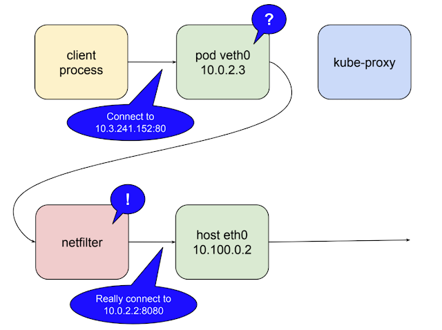
The following illustrates the role netfilter plays when kube-proxy is running as a user space proxy.
client
-> serviced IP and port e.g. (10.3.241.152:80)
--> netfilter convert to 10.100.0.2:10400
--> kube-proxy convert to 10.0.2.2:8080
kube-proxy opens a port (10400 in the example above) on the local host interface to listen for requests to the test-service
Inserts netfilter rules to reroute packets destined for the service IP to its own port.
In kubernetes 1.2 kube-proxy gained the ability to run in iptables mode. In this mode kube-proxy mostly CEASEs to be a proxy for inter-cluster connections, and instead delegates to netfilter the work of detecting packets bound for service IPs and redirecting them to pods, all of which happens in kernel space.
In sum of service networking section, by default kube-pxory runs as a systems unit, so it will be restored if it fails. The kube-proxy listens to the master API server for changes of services and endpoints in the cluster. It uses iptables to keep the netfilter rules in sync.
When a new service (svc) is created and its endpoints are populated kube-proxy gets the notification and creates the necessary rules. When it revues rule when services (svc) are deleted.
Health checks against endpoints are performed by the kubelet, another component that runs on every node, and when unhealthy endpoints are found, kubelet notifies kube-proxy via the API server and netfilter rules are edited to remove this endpoint until it becomes healthy again.
All of this add up to a highly-available cluster-wide facility for proxying requests between pods while allowing pods themselves to come and go as the needs of the cluster change.
The most basic one is that is ONLY works as described for requests that originate inside the cluster, i.e. requests from one pod to another.
For requests arriving from outside the cluster the rules OBFUSCATE the origin IP.
Ingress Networking
As above comment, we need to know how clients outside the cluster can connect to pods using the same service network.
Routing is not load balancing
"Service Network" we create from above has clusterIP as below which having no connected devices on it and implemented by kubernetes component called kube-proxy collaborating with a linux kernel module called netfilter to try and reroute traffic sent to the clusterIP so that it is sent to a healthy pod instead. In the "Service Network" the connections and reqeusts operate at OSI layer 4(tcp) or layer 7 (http, roc, etc). Netfilter rules are routing rules and they operate on IP packages at layer 3.
e.g.:
$ kubectl describe svc elastic-stack-test-kibana
Name: elastic-stack-test-kibana
Namespace: default
Labels: app=kibana
chart=kibana-0.13.1
heritage=Tiller
io.cattle.field/appId=elastic-stack-test
release=elastic-stack-test
Selector: app=kibana,release=elastic-stack-test
Type: ClusterIP
IP: 10.100.173.202
Port: <unset> 5601/TCP
TargetPort: 5601/TCP
Endpoints: 10.32.0.15:5601
Session Affinity: None
Events: <none>
Each packet destined for the service at 10.3.241.152:80 that arrives at a node’s eth0 interface is processed by netfilter, matches the rules established for our service, and is forwarded to the IP of a healthy pod. The client from outside won't be able to access 10.3.241.152:80.
We might assign it a friendly domain name, and then add a route to get those packets to one of the node. Since node is ephemeral even it's not as ephemeral as pods, router operating on layer 3 packages don't know healthy services from unhealthy. We would like to claim up from layer 3 basement to the load balancer via solution kubernetes ingress for durability.
Since this veth nice are routable thus I did setup HAProxy to try to route to those pod from external client. However, solution is not durable still since we can't easily create a stable static route between the gateway router and the nodes using the service network (clusterIP). The only other address available are ton the network the node's ethernet interfaces are connected to 10.100.0.0/24 in the example. Again it might be fail since there is not netfilter rule on those NIC IPs, they only match clusterIP on the service network. Thus the kernel will response with ECONNREFUSED. ---
- The network that netfilter is setup to forward packages for is not easily routable from the gateway to the nodes,
- and the network that is easily routable is not the one netfilter is forwarding for. ( eth0 network )
- The way to solve is to create bridge between these networks and this exactly what kubernetes does wit something called a NodePort.
NodePort Services
A service of type NodePort is a ClusterIP service with an additional capability: it is reachable at the IP address of the node as well as at the assigned cluster IP on the services network. The way this is accomplished is pretty straightforward: when kubernetes creates a NodePort service kube-proxy allocate a port in the range 30000-32767 and open this port on the eth0 interface of every node (thus the name "NodePort"). NodePorts are the fundamental mechanism by which all external traffic gets into a kubernetes cluster.
$ kubectl get svc | grep kibana
elastic-stack-test-kibana NodePort 10.104.107.199 <none> 5601:32609/TCP 19h
In above case we allocated the NodePort 32609 on physical nic (eth0) but map service ip:port (10.104.107.199:5601).
But in the diagram example, it's was allocated the port 32213. And if you have multi-nodes, all the eth0's port 32213 was allocated for physical ip ( e.g. 10.100.0.2 or 10.100.0.3 ) and traffic will get forwarded to clusterIP and port map with.
In sum, in above my case is forwarding to 10.104.107.199:5601 but in example it will be forwarded to 10.3.241.152:80 is because kube-proxy will listen port NodePort( e.g. 32213 ) then forward to service network which is 10.3.241.152:80.
Then netfilter provide rule to redirected to server pod on e.g. 10.0.2.2:8080.
In the diagram above the client connects to the load balancer via a public IP address, the load balancer selects a node and connects to it at 10.100.0.3:32213, kube-proxy receives this connection and forwards it to the service at the cluster IP 10.3.241.152:80, at which point the request matches the netfilter rules and gets redirected to the server pod on 10.0.2.2:8080. It might all seem a little complicated, and it is in some ways, but it’s hard to think of a more straightforward solution that maintains all the cool capabilities put in place by the pod and service networks.
So the issue in NodePort is exposes your service on "non-standard" port and can't set the port explicitly. Thus we need a load balancer of some kind in front of the cluster. The kubernetes platform provided two different ways to specify load balancer configuration.
LoadBalancer Service
A service of type LoadBalancer has all the capabilities of a NodePort service plus the ability to build out a complete ingress path, assuming you are running in a environment like GCP or AWS that support API-driven configuration of network resource. For example as below.
kind: Service
apiVersion: v1
metadata:
  name: service-test
spec:
  type: LoadBalancer
  selector:
    app: service_test_pod
  ports:
  - port: 80
    targetPort: http
$ kubectl get svc service-test
NAME CLUSTER-IP EXTERNAL-IP PORT(S) AGE
openvpn 10.3.241.52 35.184.97.156 80:32213/TCP 5m
Then you will see there has external-IP shows up in while you query service. That external IP is assigned by AWS or GCP. Then DNS mapping with this IP.
The limitation for LoadBalancer Service is we can't configure it to terminate https traffic. We can't do virtual hosts or path-based routing, so we can't use a single load balancer to proxy to multiple services in any practically useful way. Thus in Kubernetes 1.2 we have ingress.
Ingress
What is Ingress ? Typically, services and pods has IPs only routable by cluster network. All traffic that ends up at an edge router is either dropped or forwarded elsewhere. Conceptually, this might look like:
internet
|
------------
[ Services ]
LoadBalancer services are all about extending a single service to support external clients. By contrast an Ingress is a separate resource that configures a load balancer much more flexibly.
internet
|
[ Ingress ]
--|-----|--
[ Services ]
An Ingress is a collection of rules that allow inbound connections to reach the cluster service. It can be configured to
- give services externally-reachable URL,
- load balance traffic,
- terminate SSL,
- offer name based virtual hosting
The Ingress API supports:
- TLS termination
- virtual hosts
- path-base
An Ingress controller is responsible for fulfilling the Ingress, usually with a load balancer, though it may also configure your edge router or additional fronds to help handle the traffic in an HA manner. It can easily set up a load balancer to handle multiple backend services.
apiVersion: extensions/v1beta1
kind: Ingress
metadata:
  name: test-ingress
  annotations:
    kubernetes.io/ingress.class: "gce"
spec:
  tls:
    - secretName: my-ssl-secret
  rules:
  - host: testhost.com
    http:
      paths:
      - path: /*
        backend:
          serviceName: service-test
          servicePort: 80
The ingress controller is responsible for satisfying this request by driving resources in the environment to the necessary state. When using an Ingress you create your services as type NodePort and let the ingress controller figure out how to get traffic to the nodes.
Steps:
- In service.spec.type = NodePort
- In ingress.spec.rules.http.paths.path.backend.serivceName and servicePort which match in your k8s service configuration.
Notice: pv ( Persistence Volume ) and ing ( Ingress ) are two of the k8s module doesn't align with namespace while you are doing query e.g. kubectl get pv or kubectl get ing.
There are ingress controller implementations for GCE load balancers, AWS elastic load balancers, and for popular proxies such as nginx and haproxy. Note that mixing Ingress resources with LoadBalancer services can cause subtle issues in some environments. These can all be easily worked around, but in general its probably best just to use Ingress for even simple services.
Reference:
https://kubernetes.io/docs/concepts/services-networking/service/
https://kubernetes.io/docs/concepts/services-networking/ingress/
https://medium.com/google-cloud/understanding-kubernetes-networking-pods-7117dd28727
https://medium.com/google-cloud/understanding-kubernetes-networking-services-f0cb48e4cc82
https://medium.com/google-cloud/understanding-kubernetes-networking-ingress-1bc341c84078


